Sequoia Application Note SEQ-001-V1
Beam attenuation (c, [m-1]) is a critical inherent optical property (IOP) for oceanographers studying underwater visibility and suspended particles in the water column. Measuring beam attenuation in-situ requires transmissometers or attenuation meters, which employ an LED or laser and lens to send collimated light of a specific wavelength (or set of wavelengths) through a sample of interest. After passing through the sample, the transmitted light is typically focused by a lens through an aperture or pinhole and onto a detector for measurement (Figure 1). Comparing the amount of light measured by the detector to the amount of light initially entering the sample permits the calculation of the amount of light transmitted through or attenuated by the sample.
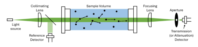
Figure 1. Example architecture of a typical transmissometer. Collimated light from a source is scattered and absorbed by the water and constituents (e.g., dissolved material, suspended particles) present in the water, reducing the amount of light making it to the detector. Forward-scattered light at small angles (dotted arrows) may also make it to the detector for measurement, biasing the attenuation measurement. The acceptance angle of the detector defines the angles of forward scattered light that are measured; it is therefore a critical parameter to know and report along with attenuation measurements.
In practice, the detector that measures the transmitted light has a finite acceptance angle (ϑa) related to the physical properties of the detector, aperture (or pinhole), and focusing lens. This acceptance angle [Jerlov, 1976, Chapter 3] is defined as:
| tan(ϑa) = (0.5*D)/f |
(1) |
D is the diameter of the aperture and f is the focal length of the lens, both in mm. Using Snell’s law to account for the change in index of refraction (n) when measuring in water and solving for ϑa [Boss et al., 2009], one gets:
| ϑa = sin-1((1/n)*sin(tan-1((0.5*D)/f))) |
(2) |
The acceptance angle of a sensor will vary between sensor types and manufacturers, which can have significant impacts on the resulting measurement. In theory, transmissometers measure light that is purely transmitted through a sample. In practice, however, the light that is measured by the detector comprises both transmitted light and small-angle forward-scattered light, where the angles of forward scattered light measured by the detector depend on the acceptance angle of the detector.
The acceptance angle therefore implies an inherent bias in beam attenuation measurements whereby larger acceptance angles result in more forward-scattered light being collected and measured by the detector. This can lead to beam attenuation values being underreported, as the sample will appear to attenuate less light than it actually does due to the additional contribution of forward-scattered light. This bias is unavoidable given the physical architecture of most transmissometers. Therefore, it is critical to include the acceptance angle of the sensor used in a study when reporting transmission and beam attenuation measurements so that researchers can accurately interpret results and intercompare across studies and sensor types.
Here we have documented the acceptance angles of our sensors that measure transmission and beam attenuation. For our calculations, we use the reported lens focal length from the manufacturer or the modeled effective focal length. For our sensors with a ring detector, where transmission is measured by light focused through a pinhole at the center of the detector array, the aperture is the average hole diameter measured across all our manufactured detectors during the quality control process (96.3 µm). For the LISST-Tau, the aperture is simply the diameter of the machined pinhole in front of the detector (~1.4 mm). For the index of refraction of water, we use n=1.34 as this is a reasonable average across realistic temperature and salinity conditions and sensor wavelengths. Table 1 summarizes the acceptance angles of relevant Sequioa sensors as well as several other commercial submersible transmissometers.
| Sensor | Lens Focal Length [mm] | Aperture Diameter [mm] | Acceptance Angle, Water [o] | Acceptance Angle, Air [o] |
| LISST-200X | 120 | 0.0963 | 0.017 | 0.023 |
| LISST-VSF* | 53 | 0.0963 | 0.039 | 0.052 |
| LISST-Deep | 120 | 0.0963 | 0.017 | 0.023 |
| LISST-Tau | 30 | 1.397 | 0.995 | 1.334 |
| LISST-SL2 | 120 | 0.0963 | 0.017 | 0.023 |
| LISST-Horizon | 120 | 0.0963 | 0.017 | 0.023 |
| LISST-100X, Type B** | – | – | 0.026 | 0.035 |
| LISST-100X, Type C** | – | – | 0.013 | 0.018 |
| C-Star*** | – | – | 1.2 | – |
| ac-9, ac-s*** | – | – | 0.93 | – |
| *Uses effective focal length due to stacked lens pair in optical assembly; supported by optical modeling. | ||||
| **https://www.sequoiasci.com/article/what-is-the-acceptance-angle-of-the-lisst-instruments/. Accessed June 01, 2026. | ||||
| ***From Boss et. al., 2009. | ||||
References
| [1] | Jerlov, N. G. (1976). Marine Optics (2nd Ed.). Elsevier Amsterdam. |
| [2] | Boss, E., Slade, W. H., Behrenfeld, M., & Dall’Olmo, G. J. O. E. (2009). Acceptance angle effects on the beam attenuation in the ocean. Optics Express, 17(3), 1535-1550. https://doi.org/10.1364/OE.17.001535. |
Application Note Version History
| 06/2026 | V1 – created and published document |
Additional Readings
Article discussing the impact of acceptance angle on transmission measurements
Previous article on acceptance angles of Sequoia’s transmission sensors
Download this Application Note as a PDF here